Passive Component Solutions for Modern Electronics Design
Discover passive component solutions designed to guide engineering decisions, enable emerging technologies, and power next-generation electronic systems.
Passive Component Solutions for Modern Electronics Design
Discover passive component solutions designed to guide engineering decisions, enable emerging technologies, and power next-generation electronic systems.


Do you want your electrical systems to run without hiccups? The answer lies in using passive electronic components. When you use them, there is no need for an external power source to boost or regulate electrical signals. The result? A smoother run for a variety of devices, ranging from precision resistors and high-density capacitors to inductors, filters, antennas, and EMI solutions. These components, although small, punch much above their weight. Find out how passive components play a stellar role across power management, signal integrity, RF design, industrial electronics, automotive systems, and IoT applications.
What are passive components?
A passive component is an electronic element that does not require an external power source to operate and cannot introduce net energy into a circuit. Passive components form the foundation of virtually every electronic circuit, from simple consumer devices to advanced industrial systems and AI hardware. Whether you’re designing power supplies, signal filters, precision timing circuits, or high-frequency RF modules, the choice of passive components directly impacts circuit stability, efficiency, size, cost, and reliability.
Why do passive components matter?
Active devices (transistors, ICs, op-amps) need passive components for their effective function. They provide the bias, decoupling, filtering, and timing infrastructure that active devices depend upon. For example, a smartphone contains hundreds of passive devices; an automotive ECU may contain thousands. A poorly specified decoupling capacitor, for example, can cause an entire system to fail EMC testing. A resistor with the wrong tolerance can shift a voltage divider enough to misread a sensor.
Core characteristics:
Main types of passive components:
The three fundamental passive building blocks are resistors, capacitors, and inductors. Each has distinct electrical properties and hundreds of subtypes optimized for different use cases.
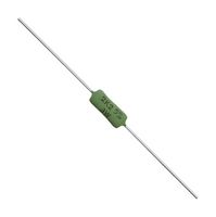
1. Resistors: A resistor opposes the flow of electrical current, converting electrical energy into heat in the process. The ratio of voltage to current through a resistor is a constant, known as its resistance, expressed in Ohms (Ω), following Ohm's Law: V = IR.
Resistors are used to set bias points, limit current through LEDs and transistors, create voltage dividers, and control signal levels throughout a circuit. Fixed value resistors are the workhorse for current limiting, voltage division, and pull-up/pull-down networks. Whereas variable resistors (potentiometers, trimmers, digital potentiometers) enable real-time or factory calibration and precision tuning.
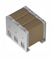
2. Capacitors: A capacitor stores electrical energy in an electrostatic field between two conductive plates separated by a dielectric material. Its ability to store charge is measured in Farads (F).
In AC circuits, capacitors exhibit reactance, which decreases as frequency increases, a property used extensively in filter design. Capacitors are used for decoupling, filtering, timing, energy storage, and power factor correction. Their subtypes include ceramic, electrolytic, film, tantalum, and supercapacitors, each optimized for voltage, frequency, ESR, or lifetime.
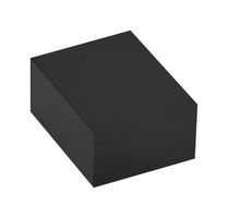
3. Inductors: An inductor stores energy in a magnetic field created by current flowing through a coil of wire. Its inductance, measured in Henries (H), describes its resistance to changes in current.
Inductors oppose rapid fluctuations in current, the complement of how capacitors oppose voltage change. They are essential for EMI filtering, DC-DC converters, impedance matching, and resonant circuits. Its subtypes range from wire-wound and multilayer chip inductors to high-current power inductors and common-mode chokes.
How passive components work in circuits:
Each passive component interacts with electrical signals in a distinct and predictable way. Understanding these interactions is the foundation of circuit analysis and design.
Impedance: The unified view
In AC circuit analysis, all three passive components are described by their impedance (Z), a generalization of resistance that accounts for frequency. Impedance is a complex quantity: its real part is resistance (R), and its imaginary part is reactance (X).
j represents the imaginary √–1, and ω is the angular frequency.
This frequency-dependent behaviour is the key to how RLC circuits create filters, resonant tanks, and timing circuits. The frequency at which capacitive and inductive reactance cancel out is the resonant frequency(fr), central to oscillator and filter design.
fr=1/2πLC
Key circuit roles:
Key differences: Passive vs active components
|
Property |
Passive Components |
Active Components |
|
Power Supply Required? |
No — operate without external supply |
Yes — require DC bias or power rail |
|
Signal Gain |
Cannot amplify. Output ≤ Input energy |
Can provide signal gain (voltage, current, or power) |
|
Examples |
Resistors, capacitors, inductors, transformers |
Transistors, MOSFETs, op-amps, diodes, ICs |
|
Primary Role |
Filter, store, divide, limit, decouple |
Amplify, switch, regulate, process |
|
Linearity |
Generally linear within rated range |
Often non-linear; linearity may require biasing |
|
Failure Modes |
Open circuit, short circuit, drift with age/temp |
Thermal runaway, ESD damage, parametric drift |
|
Typical Cost |
Very low (fractions of a cent at volume) |
Higher, especially for precision or high-power parts |
|
Noise Generation |
Thermal (Johnson) noise from resistance |
Shot noise, flicker (1/f) noise from junctions |
Real-world applications:
Module 1

Why are passive components essential? Explore how passive components evolve to meet modern circuit demands, ensuring reliability, efficiency, and innovation in design.
Module 2

What makes fixed resistors dependable? See how thick film, thin film, and metal film technologies influence construction, stability, and performance across electronic applications.
Module 3

How do variable resistors enable fine control? Learn how potentiometers, rheostats, and trimmers support tuning, calibration, and adjustment in precision electronic circuits.
Module 4

Discover capacitor technologies from MLCCs to film types, their role in energy storage and signal stability, and how to select the best fit for your circuit needs.
Module 5

Uncover how inductors regulate current, reduce ripple, and improve conversion efficiency in power supplies, filters, and electromagnetic control designs.
Module 6

Understand how filters shape bandwidth, suppress noise, and protect signal quality in measurement, communication, and high-speed electronic systems.
Module 7

Why is RFI suppression critical? Explore how RFI techniques reduce electromagnetic noise and safeguard circuit performance in high-EMI environments.
Module 8

How do antennas transform wireless signals? See how antenna design and selection impact wireless performance across RF, cellular, Wi-Fi, and IoT applications.
Module 9

What makes thermistors versatile sensors? Explore how they deliver precise thermal monitoring, enabling smart protection and control in devices.
Passive components (resistors, capacitors, inductors, and transformers) do not require an external power source to operate and can’t provide power gain; they only store, dissipate, or transfer it. They require no external DC bias or control signal to operate. Active components (transistors, op-amps, ICs) provide power gain greater than unity and depend on an external supply to amplify or switch signals. The defining threshold: if the component can deliver more signal power to the load than it receives at its input, it is active; if not, it is passive.
Passive components are deployed across virtually every electronic sub-system: RC/LC filters in analog signal chains and RF front-ends; decoupling and bulk capacitors in power distribution networks; snubber networks and EMI suppression filters in power converters; bypass capacitors and ferrite beads for high-frequency noise attenuation on PCBs; timing networks in oscillators and PLLs; impedance-matching networks in RF transceivers; and current-sensing resistors in motor drives and battery management systems.
Core passives include resistors (fixed, variable, precision thin-film, current sense), capacitors (MLCC, electrolytic, tantalum, film, supercapacitors), and inductors (wirewound, ferrite-core, power chokes). Extended passives encompass transformers, resonators (crystal, MEMS, SAW/BAW filters), varistors (MOV), thermistors (NTC/PTC), ferrite beads, fuses, and attenuators. EMC components, common-mode chokes, EMI filters are also classified as passives.
Each passive component has a temperature coefficient that directly shifts its nominal value. Resistors are rated by TCR (ppm/°C), with metal-film types achieving ±5–25 ppm/°C versus ±200–500 ppm/°C for thick-film. Capacitors are classified by dielectric temperature characteristics (C0G/NP0 ≤±30 ppm/°C; X7R ±15%; Y5V +22%/−82%), which is significant for frequency-sensitive circuits. Inductors experience permeability shifts in ferrite cores, altering inductance and increasing core losses, particularly at higher frequencies. In electrolytic capacitors, ESR rises sharply at low temperatures, reducing ripple current capability. In precision analog and RF applications, component TC selection is as critical as the nominal value itself.
Tolerance defines the maximum permissible deviation from the nominal value (±0.1%, ±1%, ±5%, ±10%, etc.) and directly governs the accuracy of derived circuit parameters. In an RC filter, if both components carry ±5% tolerance, the −3 dB cutoff frequency can deviate by up to ±10% in the worst case, which is critical in anti-aliasing or channel-select filters. In LC resonant circuits, frequency error is approximately proportional to half the sum of the relative inductance and capacitance variations, demanding tight tolerances for narrow-band RF applications. Precision circuits (instrumentation, ADC references, oscillators) mandate ±0.1%–±1% components with low TC. Worst-case and Monte Carlo analyses are used to quantify yield impact.